

In a traditional centrifugal pump, the shaft passes through the housing, and this passage is sealed with a mechanical seal. The seal is the part of the pump that fails most frequently and is the sole source of leaks. If the pump is handling acids, solvents, flammable, or toxic liquids, this leak is not just a maintenance issue; it is a matter of workplace safety, the environment, and emissions.
A magnetic drive pump solves this problem at its root: the shaft does not penetrate the housing at all. Power is transmitted through a magnetic field inside a sealed chamber. The result is a leak-free (seal-less) pump.
This guide covers the operating principles of a magnetic drive pump and the three engineering concepts that determine its selection—pole slip, eddy current loss, and dry running.
How does a magnetic coupling work?
The system consists of three parts:
- Outer rotor (drive magnet): Attached to the motor shaft, it rotates in the atmosphere.
- Containment shell (can): A single-piece, seamless vessel that completely isolates the fluid volume from the atmosphere. This is the source of the seal.
- Inner rotor (driven magnet): It is connected to the impeller and rotates within the liquid.
When the outer rotor rotates, the magnetic field passes through the containment shell, driving the inner rotor. This is a synchronous system: under normal conditions, the inner and outer rotors rotate at exactly the same speed; there is no slip.
Concept 1 — Pole-passing (decoupling)
The torque that a magnetic coupling can transmit is limited. If the load exceeds this limit, the connection between the magnets breaks: while the outer rotor continues to rotate, the inner rotor stops or rotates erratically. This is called decoupling.
This situation is not merely a loss of performance. When the connection breaks, magnetic energy is converted into heat; the decoupling chamber and the magnets heat up rapidly. If this persists, the magnets may permanently lose their magnetism, rendering the coupling completely inoperable. This is one of the most costly types of failure in magnetic pumps.
Typical causes of decoupling:
- Pumping a fluid that is denser or more viscous than expected (torque increases directly with density).
- Commissioning with a fluid whose viscosity increases in cold temperatures.
- The impeller becoming jammed by a solid object.
- Sudden valve closure or operation at very high flow rates.
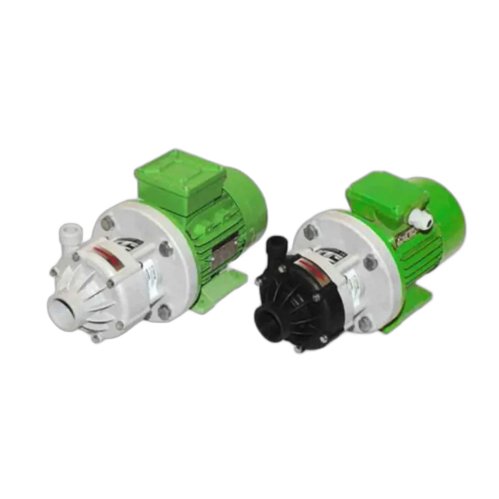
For this reason, the specific gravity limit must always be checked during selection. For example, the data sheet for our GPM Caster M thermoplastic series specifies this limit as 2 kg/dm³. It is safe for fluids up to twice the density of water; if you are planning to use a heavier solution, the model should be selected from the next higher torque class.
Protection method: A relay that monitors motor current/power can detect a loss of polarity within seconds and shut down the pump. This protection should be considered standard in critical applications.
Concept 2 — Eddy Current Loss
If the separation vessel is made of an electrically conductive metal (stainless steel, Hastelloy, etc.), the rotating magnetic field induces eddy currents within this metal. These currents result in two effects: energy loss and heating. The loss is transferred directly to the fluid as heat.
Eddy current loss increases as the vessel’s material conductivity, diameter, wall thickness, and rotational speed increase. Therefore, its effect becomes more pronounced in high-speed, large-diameter vessels.
| Separation vessel | Eddy Current Loss | Advantage | Caution |
|---|---|---|---|
| Metallic (stainless steel, Hastelloy) | Yes — causes heat and efficiency loss | Resistance to high pressure and temperature; mechanical strength | Transfers heat to the fluid; the fluid may overheat at low flow rates |
| Non-metallic (composite, ceramic, PEEK) | Practically none | Higher efficiency, no overheating issues | Lower pressure/temperature limits; sensitive to shock |
Based on this table, the following rule of thumb applies: do not operate at low flow rates for extended periods. The fluid acts as a coolant, carrying heat away from the separation chamber. If the flow rate drops too low—especially in metal-coated models—the fluid heats up, may vaporize, and bearing lubrication is compromised.
Concept 3 — Dry running: the most common cause of damage
The internal rotor of a magnetic drive pump rotates on sliding bearings lubricated by the pumped fluid itself. These bearings are typically made of silicon carbide (SiC).
SiC is extremely wear-resistant; it has a very long service life as long as it is lubricated by the fluid. However, it is brittle and sensitive to thermal shock. If the pump runs dry, both lubrication and cooling are cut off simultaneously; the heat generated by friction can crack the bearing within seconds. Carbon-graphite bearings are more tolerant of dry running, but their wear resistance is lower.
Measures to prevent dry running:
- Install a low-level switch in the suction tank and lock the pump.
- Be sure to fill the pump with fluid (prime it) before starting it; magnetic pumps are not self-priming.
- Do not operate the pump while the suction valve is closed.
- Use a power monitoring relay: it detects both dry running and phase loss.
Cavitation is a similar threat to the bearings; refer to our NPSH and cavitation guide for suction line design.
Thermoplastic or metal?
Magnetic pumps are available in two main housing families, and the selection is based on the chemical and operating conditions.
- Thermoplastic (PP / PVDF): Superior to metal in acid, base, and salt solutions. Since it is a solid material rather than a surface coating, corrosion cannot “penetrate” it. Temperature and pressure limits are lower. The GPM Caster M data sheet specifies a temperature range of −10 … +90 °C for PVDF, a system pressure of 4 bar, a capacity of 30 m³/h at 50 Hz, and a head of 25 m at 50 Hz.
- Metallic (316, Alloy 20, Hastelloy): For high temperatures, high pressures, and solvents. Hot oil, heat transfer fluids, and high-temperature processes fall within the scope of this family.
Do not base your material selection solely on the housing; consider the separation vessel and bearing materials as well; refer to our chemical compatibility guide for details.
What do the standards mean?
The practical equivalents of the standards frequently mentioned in magnetic drive pump specifications are as follows:
- ISO 2858 / DIN 24256: The dimensional standard for end-suction centrifugal pumps (connection dimensions, mounting holes, operating points). Meaning: Pumps of the same size from different manufacturers can be interchanged without modifying the installation.
- ISO 5199: The technical/performance specification for these pumps; it defines reliability criteria such as shaft deflection, bearing life, and vibration.
- API 685: The standard for seal-less centrifugal pumps for the oil, petrochemical, and gas industries. It represents the heaviest-duty class and is required for critical and hazardous applications.
Our magnetic pump category also includes centrifugal models compliant with ISO 5199, ISO 2858, DIN 24256, and API 685.
Types of Magnetic Pumps
Magnetic couplings are not exclusive to centrifugal pumps; they are combined with various hydraulic types:
- Centrifugal: High flow rate, low–medium head. General chemical transfer.
- Regenerative turbine: Low flow rate + high head. Preferred for low-viscosity liquids near their boiling point (liquefied gas, solvents).
- Gear (magnetically driven): A volumetric, leak-free solution for viscous fluids. See our guide on viscous fluid transfer for more information.
- Vane (volumetric): Applications requiring constant flow rate with low-viscosity fluids.
When to use a magnetic drive pump, and when to use a gland-sealed pump?
| Situation | Recommendation |
|---|---|
| Toxic, flammable, volatile (VOC), or carcinogenic liquids | Magnetic — no leakage path |
| Valuable/expensive product (high cost of loss) | Magnetic |
| ATEX zone, leakage emission limit | Magnetic |
| Frequent and costly packing maintenance | Magnetic — total cost of ownership decreases |
| Slurry containing abrasive solids | Packing-sealed or diaphragm-sealed — solids erode the bearings of the magnetic drive pump |
| Pipeline at risk of frequent dry runs | Packing-sealed or diaphragm-sealed; protection is required if a magnetic drive is selected |
| Very high viscosity | Positive displacement pump (gear/mono) |
The initial investment in a magnetic drive pump is higher than that of a gland-sealed pump. In return, costs associated with gland replacement, downtime, product loss, and leak cleanup are eliminated; in applications where leaks are unacceptable, this cost difference is quickly recouped.
Selection checklist
- Fluid name, concentration, operating temperature, and specific gravity (critical for torque limit).
- Viscosity—including the value at the lowest ambient temperature (start-up is the riskiest moment).
- Are there solids present? If so, a magnetic drive pump may not be the right choice.
- Operating point (flow rate + head) and system pressure.
- Material of the housing and separation chamber; if a metallic chamber is selected, allow for thermal expansion.
- Dry-run and pole-failure protection (level switch + power monitoring).
- Suction line NPSH calculation and priming procedure.
You can explore our selection of magnetic-coupled pumps with thermoplastic and metal housings in our magnetic pumps category, and by sharing your fluid data, you can receive model recommendations from our technical team.