

Selecting a vacuum pump boils down to two questions: what pressure do I need to achieve, and how long will it take—or what gas flow rate is required—to reach that pressure? Choices made without determining these two values will either fail to meet the target entirely or result in a system that is larger and more expensive than necessary.
In this guide, we compare three main technologies: liquid (water) ring, oil-sealed rotary vane, and lobe (Roots) booster. The example values provided are taken from the technical data sheets of the products we feature.
First, the units: absolute pressure and vacuum levels
Pressure in a vacuum is expressed in absolute terms: one atmosphere ≈ 1013 mbar; a perfect vacuum = 0 mbar. “The lower the pressure, the deeper the vacuum.”
| Level | Pressure range (absolute) | Typical technology |
|---|---|---|
| Coarse vacuum | 1013 – 1 mbar | Liquid ring, rotary vane, dry screw |
| Medium vacuum | 1 – 10⁻³ mbar | Two-stage vane, Roots booster combination |
| High vacuum | Below 10⁻³ mbar | Diffusion / turbomolecular (with a fore pump) |
The vast majority of industrial applications fall within the rough and medium vacuum range.
Liquid (water) ring vacuum pumps
An impeller mounted eccentrically inside the housing rotates; the service fluid (usually water) inside adheres to the housing wall due to centrifugal force, forming a liquid ring. The volume between the impeller blades and this ring expands and contracts during rotation, creating suction and discharge.
Key advantage: It is tolerant of the presence of vapor, moisture, dust, and liquid droplets in the gas being pumped. Wet processes that degrade the oil in oil-lubricated pumps do not cause problems here. Furthermore, compression is nearly isothermal; the temperature increase is minimal, which provides a safety advantage when handling flammable or explosive gases.
Critical limit: service fluid temperature
The lowest pressure a liquid-ring pump can achieve is limited by the vapor pressure of the service fluid at that temperature. Water cannot drop below its own vapor pressure—no matter how hard the pump works.
| Service fluid temperature | Vapor pressure of water ≈ lowest achievable pressure |
|---|---|
| 15 °C | ≈ 17 mbar |
| 20 °C | ≈ 23 mbar |
| 30 °C | ≈ 42 mbar |
| 40 °C | ≈ 74 mbar |
Manufacturers typically provide performance curves for service water at 15 °C. When the feed water reaches 30 °C during the summer months, both the achievable vacuum decreases and the capacity drops—because the pump expends part of its volume to carry its own water vapor.
This is the most common reason for the complaint in the field that “the pump isn’t drawing as well as it used to,” and the solution is not to replace the pump but to cool the service water (using a heat exchanger, cooling tower, or by increasing the fresh water flow rate).
If the suction pressure approaches the vapor pressure of water too closely, bubbles form and collapse in the impeller: cavitation. Operating a liquid-ring pump near its limit for an extended period causes noise, vibration, and impeller erosion. For the physics behind this phenomenon, please refer to our cavitation guide.
Our range of liquid-ring vacuum pumps includes single- and two-stage units, monoblock models, the ECO-SYS smart liquid-ring unit, and water- and oil-circulating systems.
Oil-sealed rotary vane vacuum pumps
The vanes in the eccentric rotor’s pockets are pressed against the housing by centrifugal force; the resulting reduction in cell volume compresses the gas. Oil provides sealing, lubrication, and cooling. Since the oil film seals even very fine gaps, much deeper vacuums can be achieved compared to liquid-ring pumps.
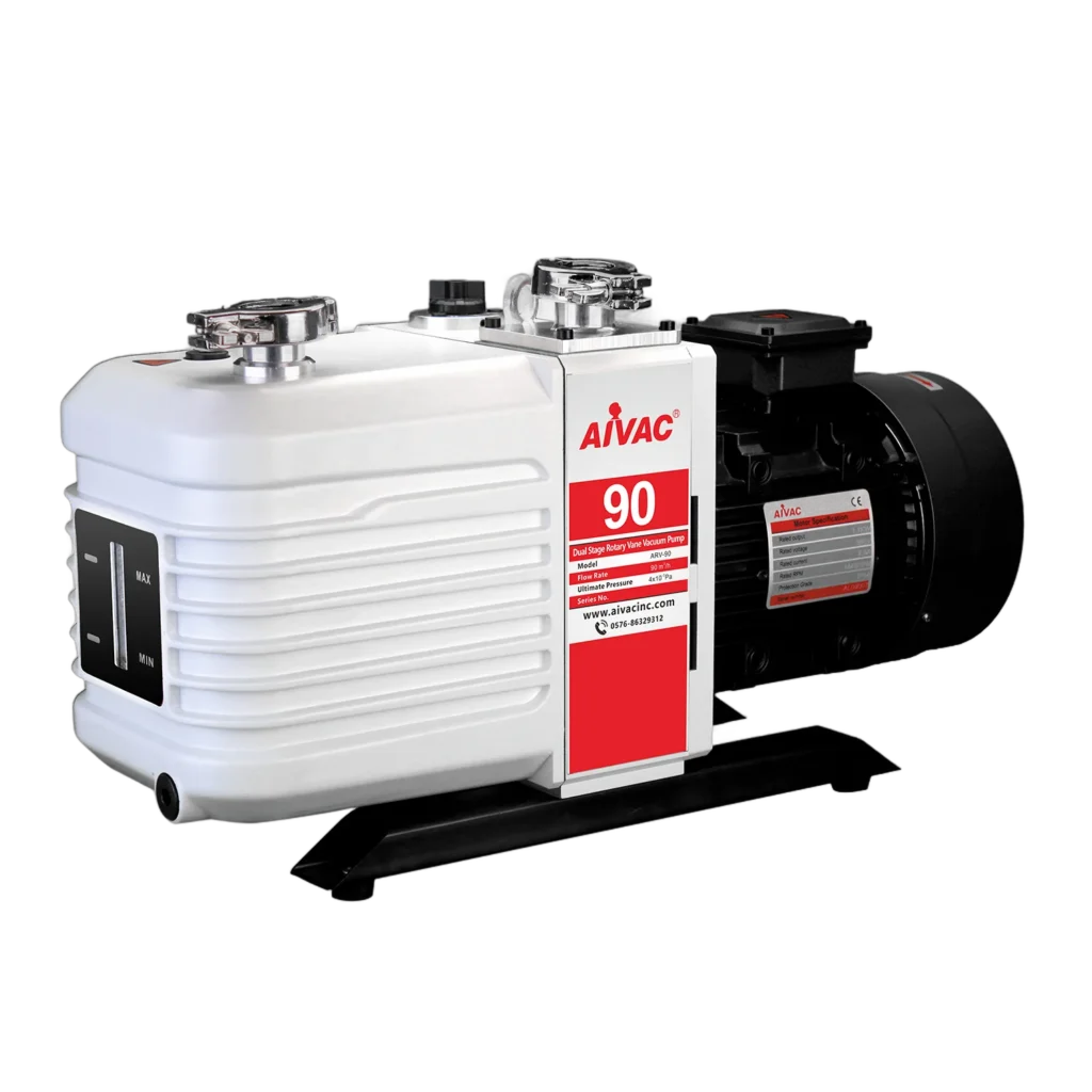
The performance specifications of the ARV-90 two-stage model in our line of oil-sealed vacuum pumps illustrate this difference:
- Nominal capacity: 90 m³/h (50 Hz) · 108 m³/h (60 Hz)
- Ultimate vacuum (gas ballast off): on the order of 10⁻⁴ mbar
- Ultimate vacuum (with gas ballast on): 4 × 10⁻³ mbar
- Motor power: 3 kW · Inlet/outlet: KF 40 · Oil capacity: 4.5 liters · Noise level: < 62 dB
Within the same product group, the VP Mini series (VP 115 – VP 2200) covers smaller capacities, while the PVP series covers higher flow rates.
What is the purpose of a gas ballast?
The greatest weakness of oil-lubricated pumps is water vapor. The vapor that is drawn in condenses during compression and mixes with the oil; the oil becomes emulsified, lubrication and sealing are compromised, and the pump loses vacuum and suffers wear.
A gas ballast introduces a controlled amount of clean air into the chamber during the compression phase. This keeps the partial pressure of the vapor below its condensation point, allowing the vapor to be expelled without condensing or mixing with the oil.
The trade-off is clearly evident in the ARV-90 data: when the gas ballast is open, the ultimate vacuum decreases from the 10⁻⁴ range to 4 × 10⁻³ mbar. In other words, in a humid process, you activate the gas ballast and sacrifice some vacuum depth. This is not a malfunction but a designed trade-off.
Practical note: Running the pump for 20–30 minutes after a wet process with the gas ballast on and the inlet closed (oil-cleaning cycle) significantly extends oil life.
Lobe (Roots) Blower and Vacuum Booster
Two non-contacting lobe rotors rotate in opposite directions via synchronous gears and displace the gas volumetrically. No oil or liquid enters the compression zone—it operates dry.
Critical point: A Roots booster cannot pressurize to atmospheric pressure on its own. The compression ratio is low; it absolutely requires a backing pump. Its function is to “multiply” the backing pump’s speed: by engaging below a certain pressure, it increases the pumping speed many times over.
Typical combinations:
- Roots + liquid ring: High flow rates in wet/contaminated processes and pressures that a liquid ring pump cannot achieve on its own. Steam processes, vacuum drying.
- Roots + oil-sealed vane: Deep vacuum + high speed in clean processes. Vacuum heat treatment, metallurgy, distillation.
Our range of lobe blowers and vacuum booster units includes the HLB helical lobe (HLB1210 – HLB2768) and TLB tri-lobe (TLB4048 – TLB4099) series, along with vacuum booster units.
Comparison table
| Criteria | Liquid-ring | Oil-sealed rotary vane | Lobe (Roots) booster |
|---|---|---|---|
| Achievable pressure | Limited by service water temperature (≈17–74 mbar) | Very low (single-stage ~10⁻², two-stage ~10⁻³–10⁻⁴ mbar) | Does not operate independently; improves the performance of the fore pump |
| Steam/moisture tolerance | Very high | Low (requires gas ballast) | High (runs dry) |
| Dust/droplet tolerance | High | Low (filter required) | Medium |
| Risk of oil contamination | None | Present (oil mist filter) | None in the compression zone |
| Maintenance | Service water management | Regular oil and filter changes | Gearbox oil, low maintenance |
| Typical applications | Paper, food, wastewater, steam processes | Packaging, CNC clamping, heat treatment, laboratory | High-volume + deep vacuum systems |
Calculating capacity
Vacuum pump capacity is a volumetric value expressed in m³/h and varies depending on pressure; it is not based on a single figure in the catalog, but rather on the pumping speed curve.
For a rough estimate of the evacuation time:
t ≈ (V ÷ S) × ln(p₁ ÷ p₂)
t: time (hours) · V: volume (m³) · S: average pumping speed (m³/h) · p₁: initial pressure, p₂: target pressure.
Example: We want to depressurize a 2 m³ tank from 1013 mbar to 100 mbar; the average pumping rate is 90 m³/h.
ln(1013 ÷ 100) = ln(10.13) ≈ 2.32
t ≈ (2 ÷ 90) × 2.32 ≈ 0.0515 hours ≈ 3.1 minutes.
This calculation is for pumping alone. In real systems, leakage load and gas/vapor load from the process are added; in steady-state operation, the pump primarily handles this load. In a line with poor sealing, sizing up the pump is not the solution—leakage must be eliminated first.
Quick Matching Based on Application
| Application | Suitable technology |
|---|---|
| Food packaging (vacuum packaging) | Oily rotary vane |
| Vacuum clamping on a CNC/machining table | Oily pallet or dry type |
| Processes involving steam and moisture, vacuum drying | Liquid ring (plus Roots if necessary) |
| Wastewater and sludge dewatering | Liquid-ring |
| Vacuum thermal treatment, metallurgy | Two-stage vane + Roots booster |
| Distillation / solvent recovery | Liquid-ring (with suitable service fluid) or Roots combination |
| Laboratory, low-volume | VP Mini-class small vane |
Maintenance considerations
- For oil-lubricated pumps: Oil color and level must be checked regularly; a milky appearance indicates the presence of water. If the oil mist (exhaust) filter becomes clogged, back pressure increases and the pump overheats.
- In liquid-ring pumps: Service water flow rate and temperature directly determine performance; scale and sediment buildup reduce capacity.
- In Roots units: The startup pressure must be adhered to; operating under excessively high pressure differentials causes overheating and rotor contact.
- For all systems: Install an appropriate filter on the suction line; dust and droplets are the pump’s most costly enemies.
If you share your target pressure, the volume to be evacuated, and the moisture/dust conditions in the process, we can work together to determine the appropriate technology and capacity. Explore our oil-sealed, water-sealed, and lobe-type vacuum units, or contact us.